Sunday, February 19, 2012

Yugo M70 Stub Demil

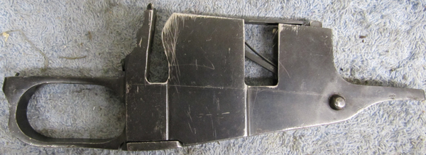
Here are some tips on how to demil the stubs of a milled Yugo. We begin with the front stub. Here we will need to take off the bullet guide and the front cover plate. The cover plate needs to come off first, before we can get to the bullet guide rivet.


Using a Dremel with the diamond bit attachment, make a small indent behind the cover plate. You now may have to remove the staking dents that partially hold the cover plate in place (on the barrel face of the receiver). Or you may just skip to the following step if they are not deep. Using a small punch, drive the plate forward.


Now, drill out the bullet guide rivet from both sides, as both are countersunk. See pics below.


NOTE TO THE WISE: If you're planning to use the take-off bullet guide in a CNC Warrior receiver - be advised that it will not fit without thinning the bullet guide "island" -- the part that mates with the receiver around the rivet hole. This is a simle task, but if you ever want to use the stubs in a reweld project, you'll have no bullet guide to use. For this reason, I chose to buy a CNC Warrior bullet guide, as these stubs might still come to life as a reweld someday, so we'd need a bullet guide that fits.


The rear stub. I won't cover removing the grip nut or the trigger guard, as that has been described elsewhere at length. That leaves the rear cover plate and the top cover button. First the rear cover plate. Using a Dremel with a diamond stone, as before make an indent behind the plate. Using a punch, drive it out.


ANOTHER NOTE TO THE WISE: If you're planning to use this take-off plate on a CNC Warrior Yugo receiver, it will not give a good fit. You're better off leaving it in place and ordering one from them.


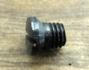
To take off top cover button, I prepared a special form screwdriver. This "donor" can be had for 1.99 at your local Harbor Freight, but feel free to use any screwdriver that you don't mind destroying. The grinding was done with a Dremel cutoff wheel, and a bench grinder for the sides.


I found it easy to grip the button in a vise.


Tuesday, September 13, 2011

Semi Auto 1919a4 build completed


We have completed a build of a semi auto version of the browning 1919a4 machine gun. It is a dirty shame that as Americans we have to put in many hours of labor in order to convert a perfectly functional machine gun, into a semi auto rifle.

The build was completed on 9/11/11 and test fired on 9/13/11. It was started more than two year ago.

We will have a detailed set of build notes published in the upcoming weeks. However since the semi auto 1919a4 build is not novel and is very well documented online, the notes will not be as thorough as before. One great word of wisdom. This build is simpler then expected. Do not be intimidated. We completed all of the machining right here at the pPharmory.

Sunday, June 5, 2011

7.62x25 Blowback - Theoretical Bolt Mass and Spring Constant Calculations

Following the example given in George M. Chinn's The Machine Gun I will apply a similar treatment to the concept of a 7.62x25 blowback-operated semi-auto.

The Measurements.

Before going further, I will summarize the measurements that will be needed in later on in the discussion and calculations. These are presented as measured by me on my 7.62x25 AK conversion consisting of an AMD-65 kit and a bolt and carrier from a Bulgy 74.

Bolt and carrier weighth (without modifications) = 475 g
Unmodified gas piston weight = 82.24 g
Custom-made full diameter gas piston = 187.60 g
Stroke length (note that my barrel sits further into the receiver than a standard AKM barrel and that the bolt is fixed in the forward position in the carrier) = 11.2 cm
Spring constant (standard AMD return spring) = 94.75 N/m

The Bolt Mass.

George Chinn begins his discussion of blowback operation by stating that for a 20mm round (this is the caliber he uses throughout the discussion) the time during which the bolt travel must be minimized is 0.0015 seconds (without case lubrication). This is the time during which the pressure (rises and) falls from its peak value to a lower value -- one at which it is safe to begin extraction of the spent cartridge. This time period is determined experimentally and depends on the cartridge material, cartridge shape, amount of gunpowder, weight of the projectile and length of the barrel among other parameters. This is the graph that George Chinn presents for the 20mm round.


At 0.0015 seconds the pressure has fallen to approximately 30% of the maximum.We will use the same threshold in our analysis below. Lacking an experimentally generated time-pressure curve I used a program called QuickLOAD which is able to generate theoretical time-pressure curves based on input of cartridge, powder and bullet parameters. This is quite a powerful (and complicated) program, though I only have access to the demo version which comes with several pre-loaded cartriges, bullets and powders. I was very happy to find that one of the presets was the 7.62x25 cartridge. So, using QuickLOAD I was able to generate the following theoretical curve of the 7.62x25 time-pressure data:


I included the full screenshot so that you can see what values I used for the multitude of QuickLOAD's parameters. All of these are default, except:

Charge weight = 0.37 g (chosen so as to give a muzzle velocity of about 1600 fps)
Barrel length = 10.5 inches (this is the length of the barrel that I will be using)

What this graph shows us is that it will take approximately 0.4 ms for the pressure to drop to 30% of the maximum. Getting back to George Chinn's example, he mentions that the maximum distance that a 20mm brass case is allowed to travel during these first few milliseconds is 0.015 inch (without lubrication). This distance is once again an empirically established value which depends on the tensile strength of the case and the amount of reinforcement near the base of case. In other words, if you pull it too far either case separation will occur or the case will split down the side without the support of the chamber walls. By visual examination of a brass 7.62x25 case, I estimated the extent of allowable movement to be 1.5 mm. This makes the maximum initial velocity for the 7.62x25 bolt:


How does this translate to bolt mass? Recall the conservation of linear momentum:


Since for a small cartridge like 7.62x25 (unlike the 20mm cartridge) the amount of powder (and therefore gas) is rather small, to simplify the treatment it will be simply dropped.

Therefore, if the mass of the projectile is 6.026 g (93 gr), the muzzle velocity is 494 m/s (1622 fps) and the initial velocity of the bolt is 3.75 m/s, the mass of the bolt must be:


This is significantly higher than the stock weight of an AK-74 bolt-carrier combo (475 g). With a 475 g bolt (and carrier) the initial velocity of the bolt becomes 6.28 m/s which, needless to say, is far too fast.

So, how can we make the bolt heavier? Well, the most obvious modification is to turn a new, full-diameter gas piston as shown in the pictures below.


The new gas piston weighed in at 187.60 g compared to the old piston's weight of 82.24 g. This gives us 105.36 g of added mass, to bring the total bolt mass to 580 g. This is an improvement but we need to get closer to 795 g. Not sure what I'm going to do yet, but I will keep you posted.

The Spring Constant.

The initial resistance to premature opening of the bolt comes almost exclusively from the bolt's mass. Once the bolt reaches its full velocity however, it is up to the return spring to bring it to a stop and send it going the other way. Schematically, the situation can be drawn in the following manner:


Where, m = mass of bolt, k = spring constant, Vinit = initial velocity of bolt, l = maximum travel (bolt stroke), x = length coordinate (zero value is marked). There is no friction and the system evolves as a function of time, t. Note that in our idealistic Hooke's law treatment, it doesn't matter whether the spring is initially compressed or not - all that matters is the additional amount of compression during the operation of the system.

What we want to know is - given a certain mass and initial velocity of the bolt, as well as a maximum travel distance, what must the spring constant be in order for the bolt to come to come to a stop at the given distance (before going back)? Alternatively, we can ask - given a certain mass and initial velocity of the bolt, as well as a spring constant, how far will the bolt travel before coming to a stop (and going back)?

The following is the derivation of the equation of motion for the bolt. You don't necessarily have to follow exactly what's going on here, as I will highlight the final equation that is of interest to us at the end of the derivation.


So, the boxed equality above is what we will use to calculate the spring constant and bolt stroke. Let's answer the first question:

"Given a certain mass and initial velocity of the bolt, as well as a maximum travel distance, what must the spring constant be in order for the bolt to come to come to a stop at the given distance (before going back)?"

For the bolt mass, let's take our heavy bolt which weighs 0.795 kg. As discussed earlier its initial velocity will be 3.75 m/s and the measured bolt stroke on my 7.62x25 AK is 0.112 m. Therefore the spring constant must be:


Note that this is about 10x the measured value of the standard AMD spring (94.8 N/m). Realistically some resistance will be provided by the hammer spring as well as by friction (and don't forget real-life deviations from Hooke's law), so the true value is likely to be lower, however it seems that at least some stiffening of the spring is needed. Currently, there is not a whole lot of options to do that however, short of making your own spring. The only readily available solution is the extra-strength Wolff spring, but that only provides 15% extra stiffness (1.15x out of the theoretical 10x). Now for the sake of discussion, let's take a look at the second question:

"Given a certain mass and initial velocity of the bolt, as well as a spring constant, how far will the bolt travel before coming to a stop (and going back)?"

Again, the bolt mass will be 0.795 kg with an initial velocity of 3.75 m/s. The spring constant will that of the standard AMD spring = 94.8 N/m. Therefore, bolt stroke will be:


This is about 3x the length of the current bolt stroke and presents a danger of the bolt/carrier combo slamming into the rear trunnion with excessive force. As mentioned earlier, a stiffer spring (or a longer receiver -- what would that look like!?) would counteract this problem but may, at the same time, introduce a new one -- where the bolt/carrier slams into the front trunnion with too much umpf on the way back. A fine balance would need to be achieved, but alas, without options in spring strength this question may remain unanswered.

In conclusion.

The mathematical analysis presented here gives a value of 795g for the ideal bolt mass in a 7.62x25 plain blowback weapon firing from a closed bolt. This is a little less than double the mass of the standard AK-74 bolt/carrier. Furthermore, restricted to the length of an AK receiver the theoretical spring constant for the return spring works out to 891 N/m, which is about ten-times the strength of the standard AKM return spring.

We can see that making a full diameter gas piston gives us about 100g extra bolt weight, however the theoretical needed-value is higher still. The stock return spring appears to be too light and while a option for a slight strengthening exists, it is limited to 115% out of the theoretically needed 1000%.

Friday, May 6, 2011

.45-70 Mosin Mag-Fed Test Fire (Video)

Here is the promised video of the mag-fed .45-70 conversions:


Voland's build is working silky-smooth, while Chapaev's will require a tiny bit more tweaking. Though in this case, the cartridge is sticking due to the case being quite rough -- these were the rounds we used for fitting, testing cycling, etc -- so the surface is full of nicks and burrs. We hope to have more video w/ accuracy results once we start reloading .45-70 and have more ammo to shoot. Stay tuned.

Wednesday, April 27, 2011

Mosin 45-70 Build Part 3 - Mag, sights work, refinish

The time for another update to this project has finally arrived. In this post we will discuss the work on the mag - turning this beast from a single shot into a 3+1 configuration. There will also be a little bit more sights work, and finally the metal will be refinished. So, without further ado, let's get started.

Here is a picture of the mag before anything was done to it:


There are two spots where the cartridge binds - in the front and in the rim areas. We had lots of thoughts of how to best modify the mag to allow it to hold the larger 45-70 cartridges. Our inclination had been towards cutting the sides off completely and welding on custom-formed sides from 4130 sheet metal. However before that could be attempted, another solution appeared on the internet (I cannot claim the original author with certainty) - whereby cuts would be made into the side of the mag to allow the rounds to fit. This solution is a lot more straightforward and much easier to implement. Therefore, it is exactly what we did.

Here is a picture of the mag with the removed sides. MAKE SURE YOU SCRIBE A LINE MARKING HOW DEEP THE MAG SITS IN THE RECEIVER. If you cut too deep you will have holes showing from below the receiver - functionally fine, but aesthetically displeasing.


I wish I had a picture to show you here with 3 rounds in the mag - unfortunately it was not taken, so you will just have to take my word for it that 3 rounds fit in very nicely. Notice how on the right side of the mag the curvy portion was not taken out like on the left side of the mag (rim area cut). This is the preferred way of doing it (leave curvy part intact on both sides), though it still works just fine as shown above.

Moving on, now comes the critical mod - magwell relief. This is not to be taken lightly, as a ruined receiver is a very costly mistake. I have to admit I was quite nervous myself as we were doing the following work.

Before:

With the first cut, the magwell was opened up just wide enough to fit the rim of the cartridge. Cut carefully, symmetrically and check fit often. Amount to cut on each side = (magwell width - rim diameter)/2. Don't remove all the material in one cut. Work up to the final dimension in several cuts while checking and measuring often.


After opening up the magwell to fit the cartridge rim, the cut was extended to allow the nose of the round to fit as well.


The last thing to do is to remove the sharp edges and to form the feedramp with a round dremel stone.


BE VERY CAREFUL NOT TO REMOVE TOO MUCH MATERIAL FOR THE FEEDRAMP. Stop early, reassemble and check. It will seem like it's binding too much, but with the mag in place things will work much better.

The above method of magwell cutting destroys the dimple that is present on the right side of the original receiver. We did one receiver each way - one has the dimple and one does not. Their feeding behavior is the same and the top round is held in the receiver (such as when you turn the rifle upside down) in both cases. If you wish to keep the dimple, carefully machine around it when enlarging the magwell. You will also have to enlarge the rim channel in the receiver with a dremel stone. Here's the dimple that I'm talking about:


With the no-dimple method, I did not modify the ejector nor the interruptor.

After being held in the mill vise, the receiver gets constricted just a tiny bit in the tail section and begins to bind the bolt in approximately this area:


Initially, I used a file to remove a tiny bit of material to allow the bolt to slide freely, but this was not necessary with a little trick that I'll show you below. Here's some pics of material removal. Dykem to mark, cycle to see where binding occurs, file.


But here's how you can avoid filing altogether. (Of course I realized this trick only as I had filed most of the material away already, heh.) Put the bolt forward so that the handle is located in the binding area and hit the bolt handle with a rubber mallet from both sides. Just firm, sharp taps - don't go too crazy. After a couple of these the binding disappears.


The last thing that needs to be done before we can try cycling a mag is to increase the angle of the follower slightly such that the nose of the cartridge aims higher when being fed. This is done by griding away a TINY BIT of metal from the follower extension, as shown in the picture below:


If you go too far and the follower aims to the sky line an anti-aircraft gun you can partially reverse the change by hammering here:


Remember, you just want the follower to aim higher by maybe 15 degrees or so - just so that it protrudes from the magwell a little. Nothing drastic.

Let's take a look at how everything looks once assembled. In the second picture below you can see the angle for the follower that I referred to earlier.


Here is a video of the mag-feed in action.


The next thing to take care of was screwing down the sights. We only ended up doing the rear sight as the hole depth had to be at least .100" in order to allow half the drilled depth to be threaded with our 6-48 bottoming tap from Midway. In the front that would have drilled away more than half the barrel thickness, so we opted to keep the front simply soldered on. Here is that process in pictures:

First align the barrel horizontally in the mill (use a level for this) and drill a hole to 0.100" depth:


Since we didn't have a tapping setup for the mill, it was done by hand. VERY CAREFULLY. You must take extra care to ensure that the tap is going in as close to vertical as possible.


Then the bolts had to be ground to size. This is kind of tricky, as it is not clear whether the reason that the bolt will not screw in further happens because it has reached the end of the hole (is too long) or the bolt's shoulder is mating with the hole shoulder (correct). To check this, take a sacrificial bolt and cut it really short - so that it won't even screw in, but rather will simply sit on top of the hole shoulder. This your guide to how far the real bolt should screw in so that it touches the hole shoulder.

To grind the bolts down, they were held in a vise-grip and ground down to approximately the size shown below:


This is how it looked after setting the screws with some red Loctite.


Ok, now to blast and park:


And finally - after through oiling and reassembly, you can see the finished product (well, not exactly finished - the stock still needs some work):


Here is a picture of both builds, or as I call them - the twins:


Stay tuned, as we still have some stock repair to tell you about - next time.