Monday, August 17, 2015

The Finnish M39 rifle as a standard reference for evaluation of bolt action rifles.

Lets walk through the superb Finnish M39 rifle using our scoring criteria from the previous post. Letters in parenthesis represents evaluation points. This rifle is not scored.

1: Overall characteristics.

The M39 is well balanced and easy to shoulder rifle. The main flaw of the M39 rifle is weight, this rifle is heavy at 9.5 pounds or 4.3 kilograms (a). In perspective a modern military carbine is about 3 kilos. Rifle length is 119 centimeters or 46.75 inches. The barrel lengths 68.7 cm or 27”. The barrel length is a healthy compromise between performance and maneuverability (b). The balance, comfort of the stock and cheek weld are excellent, the rifle has no sharp edges (c). There are several sling attachment points on the rifle allowing for varying methods of carry (d). The action is sealed against mud and snow, with no obvious points of entry. Sights have open protective ears that allow for rapid clearing of mud and snow, a very important feature (e). 
Figure 1: The M39 rifle standing next to a 100 series AK. Bottom, the M39 rifle we tested.

Conclusion: The M39 is an all around excellent bolt action rifle that is user friendly and ergonomic.

2: The bolt

The locking of the bolt is in the front of the receiver, with dual opposing lugs. The bolt body acts as a third safety locking lug, in case of locking lug failure (a). The bolt is easy to operate due to the large bolt handle. The force to lock and unlock the bolt is minimal. Bolt travel is very smooth. The bolt however is slow to manipulate, due to long throw distance and the location of the bolt handle (b). Safety is present. Safety is hard to operate and is for marching and transport, not for combat use (c). The bolt can be re-cocked in the event of a misfire, without cycling the bolt (d). No gas escape hole is provided, in the event of a pierced primer the gas would escape directly into the shooter face, this is a bad, and is a design flaw (e).
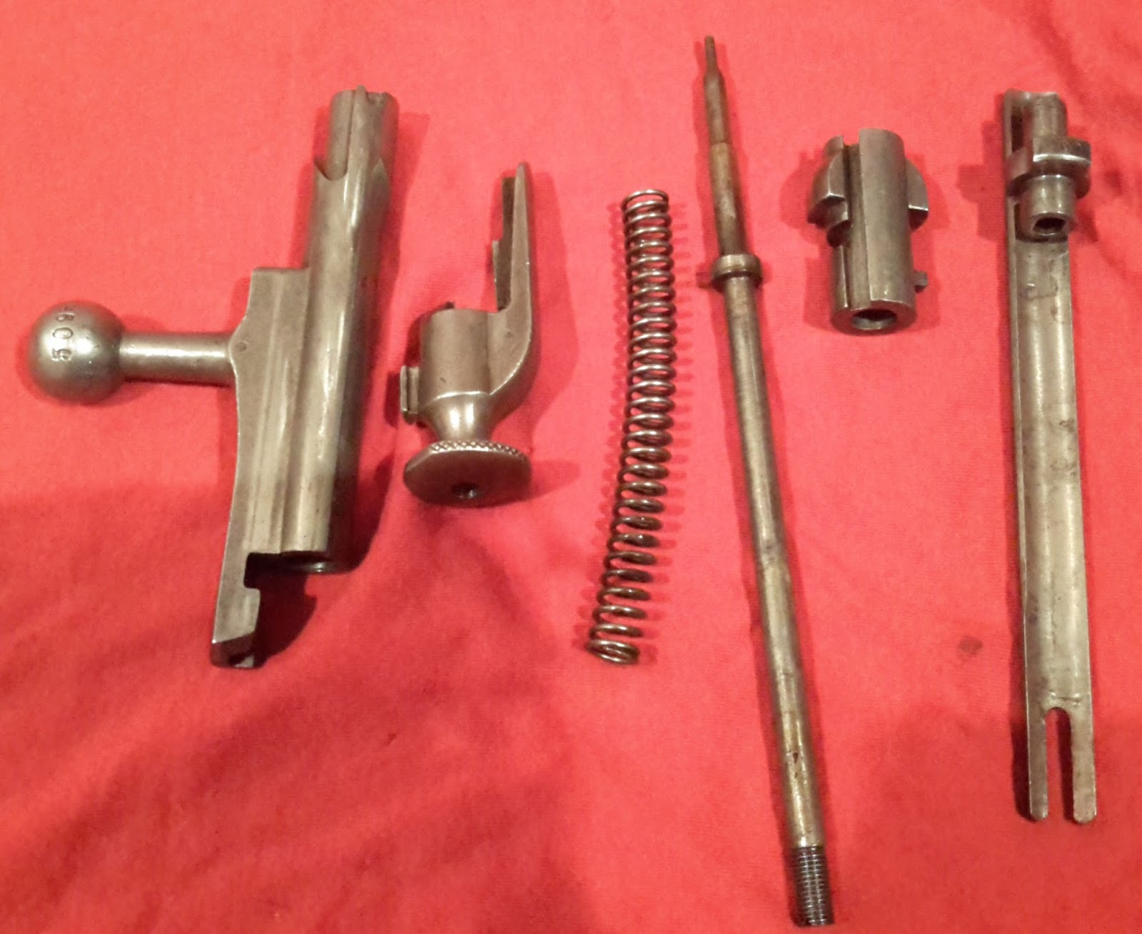
Figure 2: The Mosin bolt overall, and disassembled.

Conclusion: The bolt design is typical of late 19th century, and does not account for "modern" tactics. The lack of an easy to operate safety in particular is a concern.
3: Firing

The M39 sights are excellent, notch and post type. The sight picture is fast to acquire, and provides good contrast. The sights are adjustable for both elevation (range) and windage. The range gradations are intuitive and easy to use. Large protective ears on both the front and rear sights, provide strength and improve sight acquisition (a).The M39 trigger is superb, being a crisp two stage design; this trigger is great for delivering accurate rifle fire (b). The trigger guard has plenty of space for use with gloves. However loading the rifle with heavy gloves on from clips is problematic. shooting with a gas mask is possible, but the sight picture is poor. (c). Reloading the five round magazine (e) is accomplished using a stripper clip. The clip is easily inserted into the receiver grooves, and must be removed prior to closing the bolt. Reloading can be performed fairly fast however, due to the rimmed cartridge care must be taken on how the cartridges are arranged on the clip to avoid rim lock, this is a flaw.  The magazine can be loaded without clips, a big plus (d). 
Figure 3: M39 sight picture, safety is on.

Conclusion: The M39 is a "riflemans" rifle, great trigger, and logical easy to use sights.

"MITTENS and GAS" Part 1.


4: Field stripping

        Field stripping the M39 rifle is simplicity itself. Open the bolt, pull the trigger and remove the bolt. Remove the magazine lid by compressing a spring. Intuitive and tool free (a).  Bolt disassembly is again simplicity itself, all tool free, and very intuitive (b).  The bolt is only seven parts, six of which are easily removable in the field. The extractor should not be removed from the bolt head (c). The action can be fully accessible for cleaning by removing the bolt and the floorplate of the magazine. The floorplate is removed by compressing the spring, very easy. Reassembly is simply the reverse of assembly, and is simple intuitive and tool free (d). There are no small parts to lose. The only problem one can run into is that firing pin can be set flying if one is very careless, that’s about it (e). 
       Figure 4: The M39 bolt disassembled. Bottom, firing pin removal.


Conclusion: The Mosin rifle is a simple to use peasant proof design

5: Manufacturing

        The approximate total number of parts is 50-60, this depends on how you count (a). The most complex components that the M39 inherits from the M91 is the connector/guide rod in the bolt and the magazine as a whole. The complex components introduced by the Finns are the front and rear sight bases; they are milled and bored out, with some tough to machine shapes. The receiver of the Mosin rifle is fairly simple with only a few areas of difficult machining. A very interesting note about the Mosin receiver is that it is only partially heat treated in the front. This a great engineering solution to what in the 19th century was a very hard manufacturing problem (b). From a mass production and repair perspective, the magazine assembly as a whole with its mix of small springs and odd shapes presents a problem. The bolt design is a mass production / field repair shop dream. The separate bolt-head allows for easy repairs. Also the separate bolt head allows adaptation of the rifle to different calibers like .45-70 (Shameless plug for ourselves). Overall, and history proves this, the Mosin is a very successful easy to produce and repair design (c). The Cartridge 7.62x54r, was adopted for service in the Russian empire in 1891, it is still in active service in 2015. Without a doubt this is an excellent cartridge that has survived the test of times and is adaptable to many roles (d). The Finnish M39 rifle represents the final evolutionary branch of the bolt action rifle as the primary individual weapon. The rifle is a battle proven design, with great human engineering and ergonomics. Being of Mosin lineage, it’s a simple tool that can be issued to raw conscripts. At the same time the quality, attention to details, and modification applied by the Finns make the M39 what I would call a “Riflemans rifle”. What I mean by that is that a well-trained rifleman who knows his craft would not find this rifle lacking in any features necessary for effective use (Except for maybe the safety). Given the latter statement however it is also painfully obvious that the M39 is a boutique rifle of a small nation, and is in my opinion not scalable to mobilization and total war such as WW1. 
      Conclusion: The above gradation and discussion, should as I hope, convince you that the M39 is a good reference standard for future comparisons of rifles. The M39 is a post world war 1 modification of a ww1 rifle. Furthermore it is a rifle that was designed and built for a very capably army, with a long standing tradition of rifle marksmanship. The M39 is by no means perfect, but it is a reference.

Future posts: I spent much time debating how to approach the order in which we look at WW1 rifles. I want to avoid bias as much as possible. What came up with as a fair way to arrange the rifle reviews is in order of nations entering the war. We will start of with Austro Hungarian M1895 Steyr rifle in the next post.


Thursday, April 23, 2015

WW1 era bolt action rifle evaluation proposal.
It was a little over a hundred years ago that WW1 began. Being a firearms enthusiast, at the start of 2014 Voland began collecting WW1 main battle rifles. It will be interesting to systematically examine the designs, of these rifles, and through them get a feel for the Era. A great deal of inspiration for these series of post was from visiting two museums, The Deutsches Museum in Munich Germany and the Heeresgeschichtliches Museum in Vienna Austria. Seeing the manufacturing machinery, tools, and working conditions of the Industrial revolution in the first, and in the second seeing the morbid and fascinating exhibit dedicated to WW1.
Rational: The purpose of this experiment is to evaluate WW1 era bolt action magazine fed rifles with an unbiased and quantitative approach. It is proposed that the Finnish M39 WW2 bolt action rifle is used as a reference standard for the evaluation. The rational for use of the M39 rifle is as follows: The original design is from 1891, as such the rifle represents WW1 era design and machining capabilities. The M39 rifle is of exceptional quality, fit and finish. The M39 rifle cures many of the defects of the M1891 Mosin Nagant, and represents a refined finished product. The idea is to use a post WW1 rifle as an external reference standard.
Criteria for evaluation: The M39 will have a score of 5 for all of the categories, for a total score of 25. Each category has 5 evaluation criteria. A rifle feature that is worse than the M39 gets a -1, same gets 0, better get a +1.
1)      Overall characteristics
a.       Weight
b.      Length 
c.       Comfort (I.E. grip, carry, sharp edges)
d.      Sling points
e.      Mud (I.E. how easy is it to get mud inside the action)

2)      Bolt
a.       Locking
b.      Speed of manipulation
c.       Safety
d.      Re-cock capability
e.      Gas escape


3)      Firing
a.       Sights
b.      Trigger
c.        Reload
d.     Ammo capacity
e.      Gloves and gasmasks (Use of the rifle with both)


4)      Disassembly
a.       Tools
b.      Ease
c.       Number of parts
d.      Reassembly
e.      Parts to lose (Can we send a spring flying)

5)      Manufacturing
a.       Complexity of components
b.      Costs
c.       Cartridge
d.      Repairs
e.      Total number of parts


Note: Accuracy is absent as a criteria. It is impossible to accurately ascertain the accuracy potential in an unbiased and universal fashion. Rifles will be ~100 years old, and there is no way to account for wear. Also ammunition of original quality is no longer available. As such accuracy will be briefly considered as part of manufacturing criteria.


Note: Bayonets will not be evaluated. Maybe at a later date.

Addendum 1; Recoil has been removed as irrelevant. Use of rifle with Gloves and or gasmask has been added. A far more important aspect of rifle use.

Sunday, February 17, 2013

Semi RPD Build [Part 4] - Putting It All Together

Hello everyone, as I had promised earlier, here is the last chapter in the RPD build - Putting It All Together. In the previous 3 parts, we have made necessary modifications and have assembled all the subsystems of the RPD, and now comes the time to fully assemble the rifle and do some test firing.

We begin with the buttstock.


Onto which, the lower is installed.


Then, we install the handguards, and fasten the mounting bracket. Make sure to apply some thread locker to these.


This is what it looks like with the topcover and feed tray installed. To foreshadow a little bit, the top cover will need a little bit more fitting, but this will only be realized later.


And after all that work, here is what we finally get:


Some closeups of the individual builds:


The test-firing went smoothly for Chapaev's build, but the non-fitted top cover made itself be known for Voland's build. Now that we know the cause of the hickups, it will be fixed in short order. But without further delay, here are the videos.


Sunday, February 10, 2013

Polish AK Parts - Old vs New

Hello everyone, it's been a while since the last update. I've got a tiny bit of material to share with you before finally finishing the RPD build (it's coming).

Today we will talk about the differences between old style and new style Polish underfold parts. The differences are minor, but make for an interesting study in evolution of AK production. Before proceeding any further, I must give credit to Eric Fordon of theakforum.net for a great insight of the subject matter contained in this article.

In general, newer parts are machined, while later parts are cast with minimal machining. Here are two front sight blocks (new = top, old = bottom). Notice the casting marks, as well as some lightening "cuts" on the new style.


Here are the gas blocks. On the left is the new style, while on the right is the old.


Here are the lower hand guards. The old style is the darker one. Notice the metal horseshoe in the old, and the leaf spring in the new. Also, the old style has a serial number on the left side. The wooden tab that goes into the receiver under the barrel may be thicker on the old style.


Here are the hand guard retainers. The old style is on the left, and is milled, while the new style is on the right and is cast.


The slant breaks. The old style is on the right, while the new style is on the left. Notice the lack of what I am told is a wrench slot in the old break.


The return springs. The new style, with an anti-unlock tab is in the back, while the old style is in the front.


The rear sight blocks. RSBs are more or less identical, except for the rivet on the gas tube retainer. The old style is on the left (with a more protruding rivet), while the new style (with a flat rivet) is on the right.


Here are the top covers, but honestly I could not see much difference between them. This pair is the most distinct that I could find, with what I presume to be the old style on the bottom and the new style on the top.


Here are the trigger guards. The old style is on the left, and the new style is on the right. Notice the hump on the new style.


Here are the rear trunnions, this is probably the largest difference in parts between the old and new sets. The old style trunnion is fully milled, while the new style is stamped/bent and spot welded.


And finally, here are the folders themselves. The new style has 5 spot welds, and unequal length indents (on both sides of the spotwelds), while the old style typically has 3 spot welds and equal length indents (they look a unequal in the picture for some reason). There is an additional possibility of a combination of 5 spot welds and equal indents (not shown), it was seemingly produced under the new procedure using old parts. The loops in the bottom picture are different too, the left one being the new style, while the right one (with spotwelds) is the old style.


These are all the distinctions I could find, but I suppose I could have missed one or two :) so please don't take this to be an exhaustive list, simply what I had seen and taken pictures of.

Sunday, August 5, 2012

Semi RPD Build [Part 3] - Lower, FCG

Part 3.

In this post we will cover the modifications to the lower and FCG. The FCG was purchased from Project Guns.


Disassembly.

Firstly, strip all the wood from the lower. Knock out the trigger pin first, and remove the safety and the safety spring.


The lower will need to be cut to length.


Here is a blueprint that we will use for the next few steps. Refer back to it for dimensions as you read further.


First, mark the location of the trigger bar channel cuts. Then some material was taken out from the trigger bar channel using a dremel, so as to have less material to mill out. Be extremely careful when doing this. There is nothing wrong with milling out the entire area either, it just takes a little longer. 


Using a machinist square, mark the length of the sear pocket and the overall lower length. You can see the final markup in the second picture (the front has already been sawed off).


Now, we are ready to do some mill work - clean up the front of the lower, mill out the sear pocket, mill out trigger bar channels, mill out the round trigger bar relief. Hold the lower as shown below, and align the z-values along the x-axis, also double check consistency of y-values as x-axis is traversed.


The trigger bar channels are cut using a 1/8 carbide end mill. To start the cut - touch off on the inside of front cavity (the longer narrower one) and cut (in several passes) towards the stock. 0.125" is a sufficient width for the channel and further widening is not necessary. 

The sear pocket is milled out using a 1/4 end mill. For trimming the front, we used a 3/8 mill, but any large-enough cutter will suffice.


The following picture, shows the (almost) finished product. There is still one more cut remaining - it will be done shortly.


We can now start fitting the lower to the receiver. Using a small file, round the front of the lower as shown in the picture.


Additionally, these areas of the receiver will need to be rounded to mate with the lower.


The charging handle also needs a little filing. The areas that need to be filed are circled in red in the following picture. Also, give the flat area on the top a little work with some sandpaper.


Here is the fitted assembly.

Having fitted the lower, we can now drill the pin holes for the FCG. Here is a blueprint that we used. It is based on the blueprint was originally included with the FCG, however some values have been updated to fit the included parts. Refer to this picture for dimensions as you read the description below.


Here is a picture of the FCG itself, which includes: new rear pin, new barrel pin, screws for installing the drum bracket, trigger spring, striker, striker spring, FCG pins (there are 4, though you will only need 3), trigger bar (contains sear and disconnect), trigger bar spring, firing pin extension and firing pin extension cross-pin.


If you install the trigger bar, you will notice that it rubs against the lower in the area shown.


To accommodate this, we will mill out a relief cut in the lower. This is an inexact cut, as it is difficult to fit the ball end mill into this particular area of the lower. Using a 1/2 ball end mill, cut as long of a cut as you can manage, down the centerline of the lower. The total depth of the cut is 0.015".


Here is a picture of the trigger bar installed. Make sure it is free to move back and forth.


The trigger needs to be modified, in order to accept a trigger spring. This is accomplished by making two cuts using a 1/4 end mill. The first cut, 0.050" deep, starts from the center of the existing trigger pin hole and proceeds in a direction that is perpendicular to the nearest edge. The second cut, 0.100" deep, also starts from the center of the pin hole but proceeds at a 45 degree angle to the first. You can see both cutting directions marked in this setup picture. Center on the hole and proceed in light cuts (~ 0.010" per pass) from the center outwards.


The first cut is done.


We now, realign the trigger along the next cutting axis. Note the original mark is no longer visible, so we draw a new guide.


Center on the hole and proceed in small increments, as before.


Here is the finished trigger after some cleanup with a small file.


There is one more operation that needs to be applied to the lower - we need to drill out the return rod hole to 3/8. The setup is shown in the picture below. We use a machinist square rather than a test indicator for alignment due to the difficulty of getting the latter into the area of the measurement. The entire setup is extremely vibration-prone, since we're holding the lower by a (thick) piece of sheetmetal. For this reason it is very important to drill the hole in increments and at a small feed rate. We drilled first to 11/32 and then to 3/8.


Finally, a chamfer is applied using a scraper - a ground down triangle file.


Installation of the trigger and its spring reveals that the spring is rather long and will need to be cut to length.


Mark the area where the spring touches the lower, and using a dremel cut-off wheel make a groove just deep enough to hide the spring wire. Cut the spring to length -- careful here, cut it purposefully long and then trim to fit.


Without going into chronological detail as to how these locations were identified, I will simply show you which areas of the trigger bar were making too much contact with the trigger and its spring. You will need to file these areas just enough to clear the binding. (You will also need to file the trigger itself, so don't focus on the trigger bar alone.)


In the following picture we can see the areas of the trigger nose that will need to be fitted.


To fit the trigger, you will need to remove a significant amount of material from the top of its nose, as well as the sides of the nose (see pic below). Additionally, you will need to polish these areas to a shine, in order to ensure a smooth function of the disconnect. The entire thing must operate smoothly, no matter how hard you pull the trigger.

Here is a picture of the finished trigger.


Here is a picture of the fully-assembled FCG.


And here is a video of the FCG in action (sorry about the blur :) Stay tuned for the next post, where we will put the rifle together and do some test firing.


PS. In case of Bubba, break glass -- a short story.

Without going into details as to how this occurred, other than to say -- no it wasn't me, the lower which I had been painstakingly working on for so long was scarred by Bubba's favorite weapon - the dremel.


This was very upsetting, as the whole thing was almost finished, only to receive this horrible mark. I did not want to weld, as the location of the gauge was very close to the FCG pin hole... but how else to fill this void? And then it hit me -- soft solder. The location of the gauge is on the bottom of the lower (not a critical area) and it will be finished by parking followed by dura-coating, so there really should be no difference in the finish once the paint is applied. Here is what to do. Apply a generous drop of soft-solder to the damaged area.


Using a MAPP torch heat the solder from below, otherwise the gas pressure ends up blowing away bits of the solder. Once it melts, let go of the heat, and check for air bubbles and small voids in the filler. If necessary apply another layer of solder and melt it again. Once satisfied, take a hand scraper (like the ground triangle file from before) and scrape the bulk of the solder off. Follow by a sandpaper polish, and you will have something that looks like this:


Damage undone. Nice!