Here's something that was done 2 years ago -- keep in mind that it is still a work in progress though. What I would like to show here is an issue that is rarely addressed in people's 7.62x25 AK conversions -- excessive recoil in blowback designs. This is not the last chapter in this build by any means, however I would like to put it out there for new builders attempting their own project, as I believe it to be pertinent information. Think of this as a progress report.
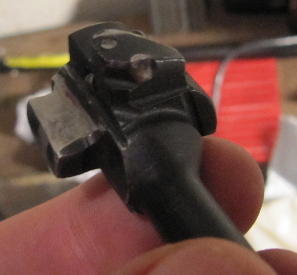
The bolt:
As you can see in the picture, the bolt was held in the forward position and a pin was drilled for and installed in the rear part of the bolt/bolt carrier. The pin was non-hardened 1/8" dowel from Enco. (The drill bit in the picture is not the one that was used for drilling). I wanted to still be able to take apart the bolt for cleaning and for that reason opted for the pin rather than welding it in place. The forward position was chosen in order to avoid laborious modification of both the carrier and the bolt. Furthermore, I was not thrilled to have the unsupported end of the bolt driving the hammer cocking process. Don't get me wrong - you can have the bolt in the rear position as well - you just have to be aware of the consequences of that design. But this is the way I did it.
The barrel, which was responsible for about half of the problems with this build, was turned from a .311 blank (yes, I have read all about the 308 vs 311 controversy and you can obviously tell where my opinion is). The turning process was begun without doing the homework on lathe operation and consequently (what can I say -- I really really wanted to get started) produced a barrel with a ridiculous amount of runout with respect to the bore. I trued it the best I could after we got our own lathe, but the damage was already done. Anyhow, here is what the barrel started it's life as (as you can surely tell, I'm using a barrel-less AMD kit acquired during The Great Scare for this build. The bolt and carrier were purchased separately). It was initially a little bit longer than 16 inches (the finished product, however, was always going to be a pistol and never had a stock fitted or installed) but was later cut down to about 11 inches.
The receiver, which constitues the source for the other half of this build's problems (more on this later) was made from a bent blank, which was modified by opening up the magwell (more on this later) and tweaking the rails. The ejector rail was moved a little bit forward, so as to place the ejector over the mag. For that purpose, I welded a sort-of extension on it, in order to facilitate spot welding it in place.
(Oh, the welder used in this build is the Harbor Freight 165A Tig. It's a pretty good machine (so far) - the lack of a foot pedal is detrimental but is not a deal breaker - you can still work without it. It is
magnitudes of order above their 90A so-called MIG).
The rail took a little bit of a beating during the installation process - while trimming the top rails, I accidentally cut into the lower ejector rail with the mill. For that reason, I removed the tail part as it was far too thin to be useful and, since the bolt is pinned to the carrier, serves no practical purpose anyway. Be careful with that mill.
The front trunnion had to be modified as well. The locking lugs were trimmed from the bottom to fit the PPS43 magwell. The bullet guide was removed so as to allow the barrel to be pressed in much further in than in the original AKM. This modification was done to facilitate more reliable feeding - the nose of the round needed to be part way into the chamber before the rest of the cartridge exited the mag.
The magwell. The PPS43 magwell was trimmed and cleaned to the point as it appears in the picture. The back tab, where it used to attach to the PPS receiver is left intact however. In the front of the magwell a piece of steel was welded on to serve as the anchor in front of the trunnion. The rear tab was (after careful measuring) was welded to the safety selector stop.
Recoil spring. After some initial test-firing (not shown) it was apparent that the blowback force was very strong (more on this later). I tried to find a stronger spring but after checking all the usual sources McMaster, Enco, Wolff - nothing satisfied me. Wolff had a 10% stronger spring, but I was looking for a little more stiffness than that. I ended up ordering several short springs from McMaster to use in addition to the existing spring. I had calculated the spring constant for the original spring and the new springs but this information has unfortunately been lost. In any case, this approach did not work as the shorter springs invariably ended up jamming inside the bolt carrier after a few shots. So, this is currently an open question - where to obtain a (much) stronger return spring that would fit an AK. At the same time, it may not even be possible to tame the recoil in this manner as the spring strength required would have to be incredibly stiff. I need to do more measurements and calculations before these questions can be answered conclusively.

. Here is a picture of the assembled pistol as it appears in the first video. What you will see in the video is a few successful shots, followed by a jam caused by the extra springs. The trigger slap is
brutal - my index finger has never experienced such pain when shooting a gun. The trigger literally slapped the shooting finger with incredible force, so much so, that I ended up using just the finger tip to pull the trigger in order to minimize the pain. Note, that the trigger, hammer and rear trunnion holes were all heat treated. The egging of the rear trunnion holes was evident after initial testing (not shown) and the heat treatment was done in response.
The first autopsy. The first thing that became apparent were the spent cases. The picture below shows what they looked like with the 16" and 11" barrels - there's not much difference between the two. The case necks are severely bulged, although there is some variation to the degree of severity. This tells me that the the pressure in the barrel is still very high when ejection begins. As the spent case is being extracted the neck loses support of the chamber walls, and due to the high pressure in the barrel expands. This observation led to the decision to cut down the barrel, in this way shortening the time that the barrel spends under pressure. However, as you can see from the picture, the case deformation did not change, indicating that the premature extraction is still just as much of a problem, even with the short barrel.

Further damage to the weapon became apparent when it was taken apart for a thorough cleaning. The trigger had a bent area that was a result of the disconnector violently slamming into it. The interface between the bolt and bolt carrier was also damaged from the recoil.
At this point, the extra recoil springs were taken out and further firing of the weapon was attempted. This, however, did not go well. After firing about one and a half mags, the receiver bowed outward. As a result, the safety selector came out of its mounting hole, at which point the weapon was no longer shootable. I fixed this problem by bending the bow back in only to have the same thing happen again less than a mag later. The bent blank receiver simply cannot stand up to the violent recoil. (The trigger slap was still a problem too).
The second autopsy. In addition to the bowing described above, the rear trunnion was literally ripping itself free from the receiver (recall that the mounting holes were heat treated).
So, this is where things currently stand. I will replace the bent blank receiver with a fully heat-treated NoDakSpud one. Furthermore, I will redo the barrel using a Green Mountain .311 barrel blank. I am still thinking whether shortening the barrel further will have any effect on the spent case deformation. Perhaps I will use this (bad) barrel as a test for the latter hypothesis.
Advice to new x25 builders/Final thoughts. Definately go with a spud receiver. You may have to figure out a way to move the ejector rail forward for reliable ejections. Consider a gas-op build, however that comes with its own set of problems. The way I feel right now however, is that 7.62x25 may be too much blowback to tame without a locking mechanism.
Hope you enjoyed reading about this build. In the next post on this subject, I hope to present you a working version of this x25 conversion.