This series of posts will deal with building a semi-auto RPD conversion from 1960s Polish kits (intact barrels). We will be using DSA receivers (though, I understand that they went off the market in early 2012) and trigger groups from Project Guns. This is a long project which was done over a week of full time building and the writeup will be split into parts, each dealing with a particular aspect of the build. I will also post some information on demiling barrel stubs from barrel-less kits.
This is by no means the first RPD build out there. In fact, there are several descriptions (of varying detail) that can be found online. The most informative and extensive is the information provided by Pirate of Project Guns, to whom we wish to express our acknowledgment. While a determined individual can find all this info from bits and pieces scattered around different sites and forums, there are many inconsistencies in the reported dimensions. Furthermore, while some aspects of the build are covered many times over (e.g. bolt carrier mods) others are not covered at all (e.g. fitting the trigger group). Thus, it is our goal to address the mentioned issues by posting our own build here, free of charge, start to finish - with all the small details.
Part I. The Bolt Carrier.
The build sequence begins with modifications to the bolt carrier, as it will allow us to start fitting parts together in the receiver. The fitting of the bolt, the charging handle and headspacing will all depend on a functioning bolt carrier. Another note that should be made here is that the first thing you want to do to the bolt carrier is to machine away the hammer island, so as to prevent full auto functionality before anything else is done. (Admittedly, this was an oversight on our part and we did not follow this order. Learn from our mistakes, do it the right way yourself.)
As this will be your first machining operation of this build -- make sure to check the alignment of your machine, in particular the alignment of the mill vise (unless your vise is keyed, but even then it would be a good idea). We will still align each part individually, but it helps to start with a fully square setup. Also -- make sure you've trammed your mill recently.
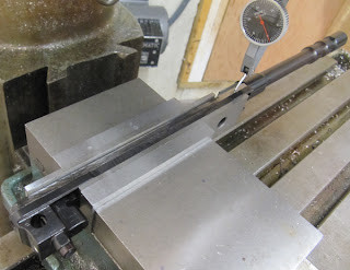
This is a pretty easy cut, but still take care to level the carrier with a test indicator. If you followed the steps above, it will probably suffice to level only along the x-axis. Here is the setup:
You will be removing 0.100" from the face to give the final measurement of 1.162" (see pic). Use a 3/8 in mill for this.
Here is the final product:
Now we move on to trimming the rails. See the pictures for illustration of the setup. Leveling is done on the two edges highlighted in red. Note that this is done before milling off the sear catch, as that area is good to grab onto for clamping the carrier in the vise.
Just to be clear, we are trimming the lower side of the rails -- see schematic above. Amount to cut is 0.025". This cut was done with a 3/8 end mill. Here is the final product. The other side is done in analogous manner.
Now, we do the sear catch. Once again, here's the setup, with edges to level on highlighted in red. You will be cutting away just enough material to widen the sear channel to uniform width.
After the cut -- using a 1/2 in end mill:
Next step is to drill the firing pin extension (FPE) hole. This is a bit tricky due to the setup, and you will need 4 123-blocks, the usual mill clamping kit and (this is the key part) a precision angle with bolt slots (or something similar). We barely had enough room on our mill to clear this setup. If all else failed, the gas piston could have been taken off, but we really wanted to avoid that. The dimensions for the hole location are given below along with the location for the cross pin (as the picture states, these numbers are from the Project Guns website).
Here is the setup for drilling the FPE hole.
First drill with a 0.185" bit (#13). Then finish with a 0.189" reamer.
As you can see, the FPE ends up being a bit low with respect to the firing pin, however the contact area is sufficient for perfect functionality. Furthermore, positioning this hole higher is a risky proposition because there is not much material as it is between the FPE hole and the top of the bolt carrier. Although, if doing it again, I would move the center up maybe 0.005 or 0.010".
Having done the FPE, we can now do the cross pin. Here is the setup.
Again, drill to 0.116" bit (#32) then ream to 0.1247".
My markup ended up being a thou or two high, so I had to file a little bit of material from the FPE (see pic). This steel is extremely hard to file by hand, but a sandpaper dremel wheel does the trick nicely.
Here is the final product
Make sure the FPE is completely free to move. With this, we will move on to the barrel, bolt and headspacing.


No comments:
Post a Comment