Showing posts with label .45-70 Govt. Show all posts

Wednesday, April 27, 2011

Mosin 45-70 Build Part 3 - Mag, sights work, refinish

The time for another update to this project has finally arrived. In this post we will discuss the work on the mag - turning this beast from a single shot into a 3+1 configuration. There will also be a little bit more sights work, and finally the metal will be refinished. So, without further ado, let's get started.

Here is a picture of the mag before anything was done to it:


There are two spots where the cartridge binds - in the front and in the rim areas. We had lots of thoughts of how to best modify the mag to allow it to hold the larger 45-70 cartridges. Our inclination had been towards cutting the sides off completely and welding on custom-formed sides from 4130 sheet metal. However before that could be attempted, another solution appeared on the internet (I cannot claim the original author with certainty) - whereby cuts would be made into the side of the mag to allow the rounds to fit. This solution is a lot more straightforward and much easier to implement. Therefore, it is exactly what we did.

Here is a picture of the mag with the removed sides. MAKE SURE YOU SCRIBE A LINE MARKING HOW DEEP THE MAG SITS IN THE RECEIVER. If you cut too deep you will have holes showing from below the receiver - functionally fine, but aesthetically displeasing.

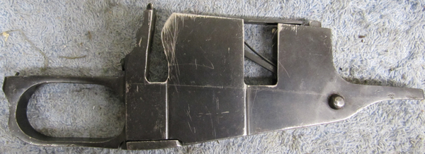

I wish I had a picture to show you here with 3 rounds in the mag - unfortunately it was not taken, so you will just have to take my word for it that 3 rounds fit in very nicely. Notice how on the right side of the mag the curvy portion was not taken out like on the left side of the mag (rim area cut). This is the preferred way of doing it (leave curvy part intact on both sides), though it still works just fine as shown above.

Moving on, now comes the critical mod - magwell relief. This is not to be taken lightly, as a ruined receiver is a very costly mistake. I have to admit I was quite nervous myself as we were doing the following work.

Before:

With the first cut, the magwell was opened up just wide enough to fit the rim of the cartridge. Cut carefully, symmetrically and check fit often. Amount to cut on each side = (magwell width - rim diameter)/2. Don't remove all the material in one cut. Work up to the final dimension in several cuts while checking and measuring often.


After opening up the magwell to fit the cartridge rim, the cut was extended to allow the nose of the round to fit as well.


The last thing to do is to remove the sharp edges and to form the feedramp with a round dremel stone.


BE VERY CAREFUL NOT TO REMOVE TOO MUCH MATERIAL FOR THE FEEDRAMP. Stop early, reassemble and check. It will seem like it's binding too much, but with the mag in place things will work much better.

The above method of magwell cutting destroys the dimple that is present on the right side of the original receiver. We did one receiver each way - one has the dimple and one does not. Their feeding behavior is the same and the top round is held in the receiver (such as when you turn the rifle upside down) in both cases. If you wish to keep the dimple, carefully machine around it when enlarging the magwell. You will also have to enlarge the rim channel in the receiver with a dremel stone. Here's the dimple that I'm talking about:


With the no-dimple method, I did not modify the ejector nor the interruptor.

After being held in the mill vise, the receiver gets constricted just a tiny bit in the tail section and begins to bind the bolt in approximately this area:


Initially, I used a file to remove a tiny bit of material to allow the bolt to slide freely, but this was not necessary with a little trick that I'll show you below. Here's some pics of material removal. Dykem to mark, cycle to see where binding occurs, file.


But here's how you can avoid filing altogether. (Of course I realized this trick only as I had filed most of the material away already, heh.) Put the bolt forward so that the handle is located in the binding area and hit the bolt handle with a rubber mallet from both sides. Just firm, sharp taps - don't go too crazy. After a couple of these the binding disappears.


The last thing that needs to be done before we can try cycling a mag is to increase the angle of the follower slightly such that the nose of the cartridge aims higher when being fed. This is done by griding away a TINY BIT of metal from the follower extension, as shown in the picture below:


If you go too far and the follower aims to the sky line an anti-aircraft gun you can partially reverse the change by hammering here:


Remember, you just want the follower to aim higher by maybe 15 degrees or so - just so that it protrudes from the magwell a little. Nothing drastic.

Let's take a look at how everything looks once assembled. In the second picture below you can see the angle for the follower that I referred to earlier.


Here is a video of the mag-feed in action.


The next thing to take care of was screwing down the sights. We only ended up doing the rear sight as the hole depth had to be at least .100" in order to allow half the drilled depth to be threaded with our 6-48 bottoming tap from Midway. In the front that would have drilled away more than half the barrel thickness, so we opted to keep the front simply soldered on. Here is that process in pictures:

First align the barrel horizontally in the mill (use a level for this) and drill a hole to 0.100" depth:


Since we didn't have a tapping setup for the mill, it was done by hand. VERY CAREFULLY. You must take extra care to ensure that the tap is going in as close to vertical as possible.


Then the bolts had to be ground to size. This is kind of tricky, as it is not clear whether the reason that the bolt will not screw in further happens because it has reached the end of the hole (is too long) or the bolt's shoulder is mating with the hole shoulder (correct). To check this, take a sacrificial bolt and cut it really short - so that it won't even screw in, but rather will simply sit on top of the hole shoulder. This your guide to how far the real bolt should screw in so that it touches the hole shoulder.

To grind the bolts down, they were held in a vise-grip and ground down to approximately the size shown below:

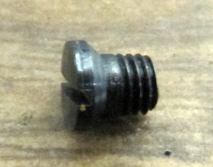

This is how it looked after setting the screws with some red Loctite.


Ok, now to blast and park:


And finally - after through oiling and reassembly, you can see the finished product (well, not exactly finished - the stock still needs some work):


Here is a picture of both builds, or as I call them - the twins:


Stay tuned, as we still have some stock repair to tell you about - next time.

Sunday, January 23, 2011

Mosin .45-70 Build Part 2 - Extractor Relief, Sights, Stock Inletting

So, this is a little bit delayed but it's a good update so it's worth the wait. As you may recall, the last build session ended with a barreled (but not tightened) receiver. This time we will continue the process with:

1. Extractor relief cut
2. Sights installation
3. Stock fitting

Here's the obligaotry "before" pic:


I made two barrel timing marks, one for a hand-tight fit and one for the final fit.
Here's the hand tight:

And here it is after tightening with a home-made action wrench and barrel blocks:

Looks like it went from about 0 to 2 o'clock, which I guess is kind of far (0 to 1 o'clock is desired). I suspect that the reason behind it is that the barrel shoulder wasn't sharp enough (90 degree ideal). No matter, it just had to be tightened a little further. At this point, another mark is made on the barrel to indicate how far to twitst to full-tight.


After marking the wrench-tight degree of twist we unscrew the barrel and mark the area to be removed for extractor relief. What should the extractor relief look like? Here's what an 91/30 izzy barrel barrel looks like. The 6 o'clock in the picture below corresponds to the bottom of the receiver. I am using a piece of steel wire to indicate the vertical center line. From here you can get an idea of the angular extent to which the extractor relief thould be cut (~135 degrees out of 360).


I then transferred the markings as faithfully as I could to the barrel blank. The extractor cut will be made in the mill. We do not have an indexing head and so this is the trick we used instead. The following picture shows an aluminum bar that I used to practice the cut before performing it on the barrel.


Notice the workstop in the back - this is what allows us to turn the bar in the mill vise without disrupting its position along the mill table. I will not show my practice work, but will instead move on to what I did to the barrel. First, the setup:


Here's where you want to zero the cutter by touching the top and face of the barrel. We will work by moving the cutter to and from ourselves. I started by making all sorts of fancy measurements on the factory barrel, but ultimately ended up simply taking the barrel out of the vise and checking it against the bolt until the extractor was cleared. Here are some pictures of the progress. You can also get an idea of how I was making the cuts from these.


This was supposed to clear the extractor according to my measurements, but alas. The pointy extractor tip was coming up against the surface cut in the last step above. I ended up having to remove most of that material in order to allow for sufficient extractor clearance. The removal was done in the same way as before. The "lip" went from this:

to this:

The lip is indeed pretty thin. Perhaps using a larger diameter endmill will allow more material to remain. I used a 1/8" ball-nose end mill for all the above operations.


The crown was done with Midway's .30 cal crowning tool (here) fitted with a custom-made (from an old Harbor Freight brass punch) pilot bushing. At this point, the barrel was screwed back in to the receiver to the wrench-tight mark made previously. It was now time to take care of the sights. The sights were ordered from Numrich - it was a cat-in-a-bag purchase, but ended up being discounted Williams front+rear sight combo (also available from Midway and Brownells). Make sure they are steel. Voland ordered his rear sight elsewhere and it turned out to be made from aluminum. As a result, we weren't able to solder it to the barrel. The curvature on the bottom had to be tediously fitted to the actual barrel diameter by running them over some sandpaper, which in turn was wrapped around the barrel. (I got some really bad blisters while doing this).


After a quick sanding of the surfaces to be mated, they were degreased with mineral spirits (not the best solvent for this - use acetone if you have it). For the solder we used soft solder from Midway (here) and this is how much I ended up putting on the bottom of the front sight. In retrospect I would say use about twice as much.


The sights were clamped onto the barrel with a C-clamp and heated with a mapp-gas torch. It took quite a bit of heat to get the solder to melt - it made me wish for an oxygen setup to speed things up. Embarassing note: even though I took the time to make sure the sights were "straight" they still ended up being "crooked". Here's a pic of the crooked front sight after soldering.

The fix? Take 'em off and do it again. Here are some pics of the solder after the sights were taken off.


The front sight has enough solder, but the rear is definately insufficient. The old solder was then sanded off and the soldering process was repeated, this time with much better results. Actually, I am skipping a step here, as chronologically - the stock was fitted before the sights were redone. I strongly recommend doing future builds in this order - that is - first stock then sights, as being able to put the action in the stock makes sight alignment much easier. Anyhow, here's wha the redone sights looked like:


Here is the stock fitting step that preceded the final sights installation. The stock was originally slightly longer than the end of the barrel, and for that reason it was chopped right in front of the front sling slot. The new barrel diameter was much larger than the original barrel channel and in order to make it fit material had to be removed. There are fancy tools out there for doing this, however, for doing only one build I chose to rely on the ol' sandpaper-aluminum pipe method. Pick a pipe with a diameter that is similar to the new barrel, wrap some coarse sandpaper around it and get to work. I also used a dremel with a large diameter stone for difficult to get areas.


This is what the rifle looked like after chopping the stock. Kind of ugly and bubba-esque.


The fitting process.

An intermediate stage in the inletting process.

After trimming to size, the front piece of the stock was re-attached as follows. Two holes were drilled into the main stock, into which two pieces of thick copper wire were inserted (with glue). I used a non-specialty glue that we had on hand - you on the other hand should spend some time and get the proper wood glue for this operation. To mark the location of the holes on the front piece, it was aligned and hit gently with a rubber mallet so that the copper wires make a mark on the wood. Holes were then drilled and the two pieces of stock were joined as shown below. A generous amount of glue was added between the two stock pieces.


(You can see the glue we used in the above picture)

After the glue had dried, this is what the joint looked like up close. The front piece then needed to be inletted in the same manner as the rest of the stock.


And here is a picture of the assembled rifle!

Now, it was time for a test fire!


The weather was very cold and beautiful, so I couldn't resist taking some artistic shots ;) Without any sights adjustments the rifle shot pretty close to center right out of the shop. After taking a few more shots I had the rifle dialed in almost perfectly. Later on, while transporting it to the range, the rear sight did come loose as the holding screws on it are very flimsy. I will stake it in place at a later date.


Finally, I will leave you with some action shots of the 45-70 Mosin vs a bowling pin. This was from a little less than 25 yards. Hope you enjoyed this long-overdue writeup. I'm looking forward to the next part of this build where we will work on the magazine and possibly stock refinishing and restoration.